Sunday, August 28, 2005
Empire plinth
Building a new plinth out of Corian.
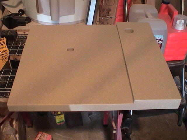
I bought two 1/2 thick pieces from Ebay. Cut them down a little, and then glued them together.
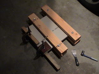
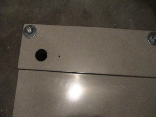
I glued one of the cut pieces to one side, because I need to raise my tonearm for the thick empire platter. Drilled holes for the arm and spindle. I used a wood hole saw to drill the hole for the arm, but I wish I would have done it differently. Hole came out a little large, and I have to put electrical tape around my VTAF to make it snug.

Tooks lots of sanding to get to this point. I sended the edges starting with 60 grit with my orbital sander, to get it even. It was not even after I glued it together. I worked my way down to 2500 grit (from an auto paint supply store), and finished with rubbing compound. Lots of work, but I was happy with the results.
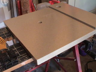
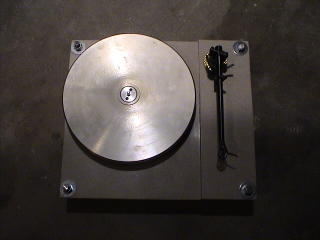
Ready for the tonearm.
Legs are made from 1/2 inch "all thread", bought from home depot.
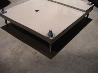
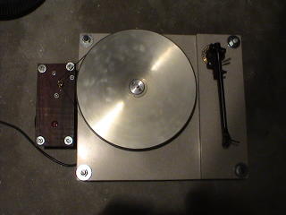
With the motor attached, it spins ;).
I bought two 1/2 thick pieces from Ebay. Cut them down a little, and then glued them together.

I glued one of the cut pieces to one side, because I need to raise my tonearm for the thick empire platter. Drilled holes for the arm and spindle. I used a wood hole saw to drill the hole for the arm, but I wish I would have done it differently. Hole came out a little large, and I have to put electrical tape around my VTAF to make it snug.
Tooks lots of sanding to get to this point. I sended the edges starting with 60 grit with my orbital sander, to get it even. It was not even after I glued it together. I worked my way down to 2500 grit (from an auto paint supply store), and finished with rubbing compound. Lots of work, but I was happy with the results.

Ready for the tonearm.

Legs are made from 1/2 inch "all thread", bought from home depot.

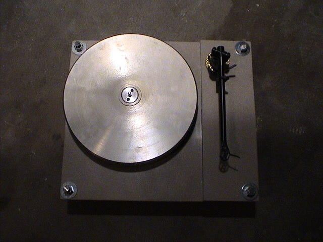
With the motor attached, it spins ;).

Saturday, August 13, 2005
Empire Turntable - Motor
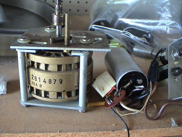
So, here is the motor and everything else, after I pulled it out of the table. I traced the wires, and drew a simple schematic for it.
I ended up changing the power cord, because it was so old, and had a very cheesy plug on it. I was going to put in a bigger motor run cap in it as well, but then I saw somewhere that the motor is designed for a certain capacitance, which is on the motor. And the motor says 4 uf, which is what Empire used. So, since it works, I just left the old cap in.
Now, I was trying to figure out how to mount the motor. I wanted to not have it part of the plinth, which is different from how it came. It was isolated on three rubber mounts, but it is connected to the top, with the rubber mounts, in the original table.
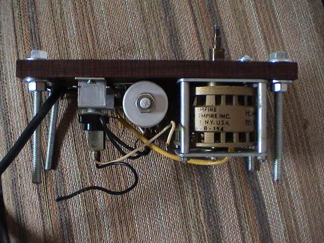
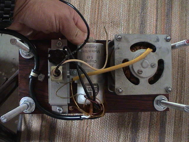
I had a piece of 1/2' thick cocobola I was going to use for the armboard, but ended up doing something else, so I just mounted the motor to this piece of wood. I drilled out a few holes to screw the motor in, and one big hole for the spindle. I used thread all for the 4 legs.
I ended up removing the top plate from the motor assembly, this is the plate that allows the motor to move, with a spring to adjust the tension. It is meant to maintain the right tension on the belt. I figured I could just move the motor farther away if the belt gets loose.
That's it for now. Here are some pics.
My biggest mistake for this is I was not carefull when I drilled the holes for the legs, and one leg is crooked :(.


Rega RB-250 Tonearm mods
Rega RB-250 tonearm mods
Structural mod
That is what origin live calls their version of this change, but is really is just changing out the cheap plastic end stub with a metal one, and using a better counterweight.
I picked the Michell counterweight, as reviewed here
http://www.vinylengine.com/michell_tecnoweight.shtml
It was not cheap, but I liked it because it is easier to adjust the counterweight on it. It was a scale built in, versus the others where you just move it back and forth, and need a scale to set it.
Rewiring
I also rewired my arm. I got the arm cheap because it had an intermittent wire, so I just changed it out.
There are many pages out there that talk about rewiring regas, here are some links
http://www.hi-fi.com/diy/rega/
http://melhuish.org/audio/rewire.html
http://csown.dhs.org/hi-fi/rega_mod.html
And, here is what I did. Sorry, did not take pics while I was doing it.
I decided to use the Cardas tonearm wire from Percy for this job. Some people advocate the discovery wire, and solid silver wire, but I was worried about how this wire would effect tracking. Cardas is only 33 ga wire, and it is stranded to make it more flexible.
First, I removed the rubber stop from the bottom of the arm, and cut the wires at the little circuit card that is attached to the rubber. I cut the card off, and just saved the rubber stopper.
I tried to solder my old wire to the new wire, but when I tried to pull the new wire through with this method, it just broke the old wires, and broke the ground wire to boot. The tonearm ground wire went from the little circuit card to a little copper piece that is close to where the end stub screws into the arm. The copper is wedged into the arm to make ground contact there.
I ended up running a piece of 30 gauge solid wire through the arm. It is pretty easy if you remove the end stub, and start from the bottom.
I then soldered the new wires to the 30 gauge wire, and pulled them through. It worked, but it was a little too fat at the solder point, so it pulled out to little rubber gaskets, one a little before the wires enter the bearing area, and one where the wires enter the tonearm tube. The point of these gaskets is to make sure the wires don’t mess up the bearing movement, I think.
I was able to pull the new wires back and forth, to get the rubber gaskets back in place.
I used a piece of solid 30 gauge wire for the ground wire. I soldered it to the same copper piece the old ground went to.
I drilled a small hole in the rubber stop, and pulled the tonearm wires though the stop, as well as the ground wire.
I carefully soldered clips on to the wires at the headshell. I reused the rubber piece that was there, to run the wires through.
I then pulled them back, to leave just enough at that end. Then, I put the rubber stop in at the bottom of the arm, but stuffed a little wire in at the bottom, for a service loop.
For now, I taped the wires to the rubber stop, where they come out of it. This is temporary, and I will glue them in place, as soon as I am sure it is all working ok.
I put on Eichman bullet plugs on the other ends. For a phono plug, the low mass design of the RCA’s makes sense to me.
I did not shield at all, was a little worried, but no noise when I connected.
Also, tracks fine. I was worried about how it would track after I rewired, but played a few albums, and they had no problem at all.
![]()