Thursday, September 18, 2014
Modding Silverstone PCIE USB card
Instead of buying an “audiophile” usb card, I decided to buy a Silverstone EC04-P PCIE to USB card and mod it. They also make a EC01-p with two internal USB ports only, but with that one you need to figure out how to connect the USB port to your DAC. With the EC04-P, since it has two external ports it's easy.
This mod is based on info from these threads:
xxhighend forum threadThe mod isolates the 3.3VDC from the PC, and provides a separate 3.3V generated from a linear reg I added on the board.

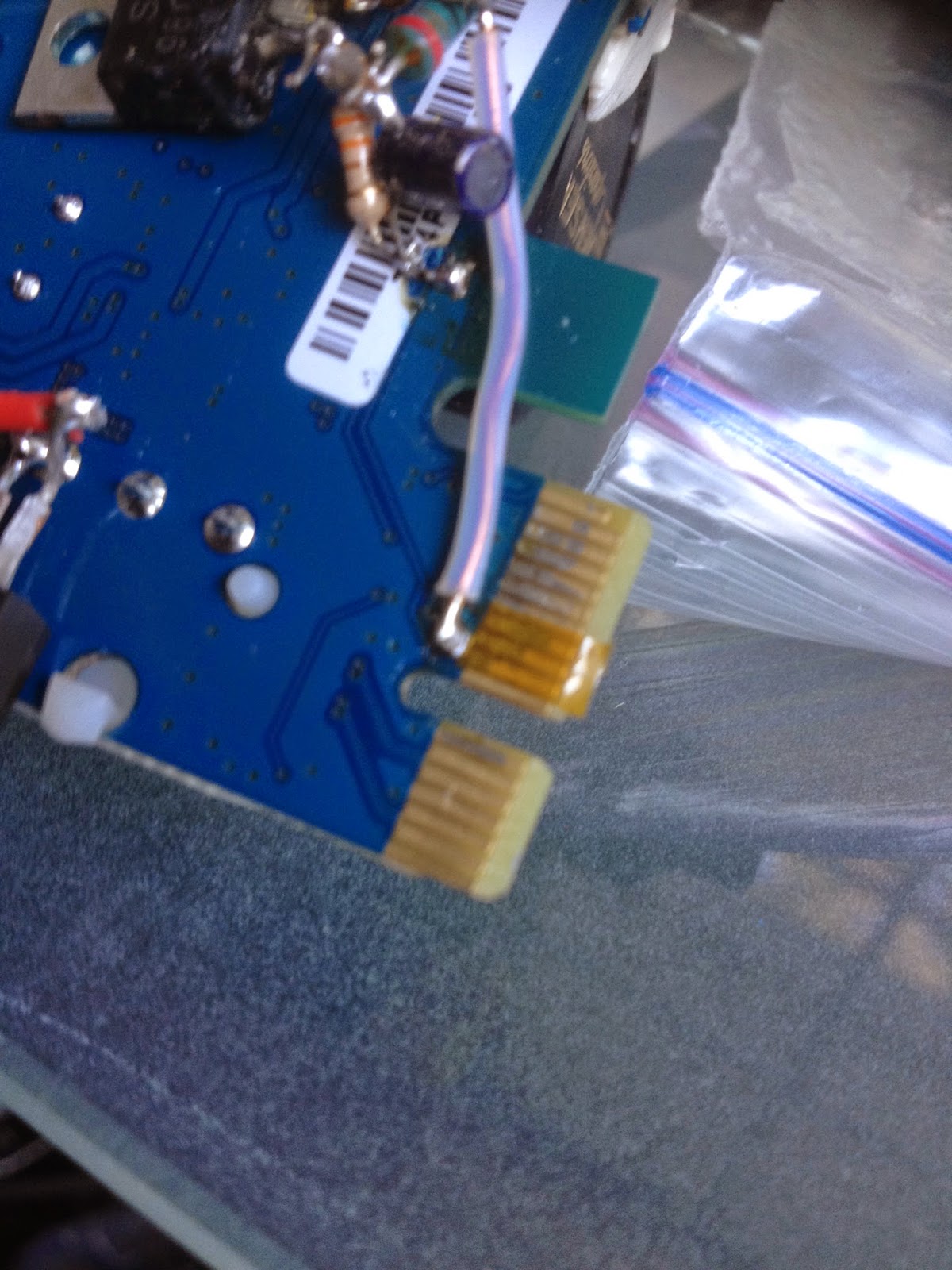
These pictures show where the 3.3 pins are. Two 3.3 pins to the left here. BTW, at the point right next to these pins, I scrapped away the solder mask, and connected the 3.3V from my voltage regulator.
When you cover these pins with tape, you can cover the JTAG pin below the 3.3V, but do not cover the Power Good pin above the 3.3V, things stop working.
The other 3.3V pin is here. This one is easy because you can cover the pins above and below with no side effects.
Initially I added a dc jack on the bracket, and then connect a little walwart to feed it about 11 VDC. I needed at least 7VDC, and this is what I had in my stash.
 Then I needed the DC jack for something else, before I had time to buy more, so I scavenged this one, and soldered the walwart leads directly to the card. It’s like that for now, but I intend to change it soon.
 I added a LM7805 linear voltage regulator to power the molex jack on the usb card. Without the 7805, I had to connect a molex from the PC power supply to make things work. The 7805 provided a fixed +5VDC on the USB out. With my DAC, the +5 from USB is not used. I have an Amanero USB to I2S card, and it is powered from the main DAC board.
The 7805 is in the bottom left of this picture.

The rest of the mod isolates the card from the main 3.3V, and supplies power from a dedicated regulator.
I used kapton tape is isolate the 3.3V pins at the PCIE connector to the motherboard. Now that it works, I may make etch cuts with an exacto knife so I don’t have to mess with the tape. Then I made a little 3.3V regulator using a LM317 adjustable reg.
Scraped off some solder mask to expose copper to solder to so I could connect the 3.3V from the 317 to the USB card. In the picture above, you can see the point right above the isolated pins where I scraped off some solder mask, and connected the 3.3V from the voltage reg. I connected ground by my power connector, you can just see it at the top left part in the picture above.
There is also one pin on the other side that is taped over that you can't see.
Plugged it into my PC, then plugged the DC jack into the card, and then turned on the PC. I plugged a USB mouse into the card first to test it. The mouse worked, so I plugged my dac in, and it works.
Future mods in consideration include a clock upgrade for the
24 MHz clock and trying a better 3.3V reg.
It sounds quite a bit better than the motherboard USB port, worthwhile mod. Note that I did this before I added a linear 3.3V power supply, the benefit might be smaller, but I still think it is beneficial to have a separate 3.3V regulator for this card.
It sounds quite a bit better than the motherboard USB port, worthwhile mod. Note that I did this before I added a linear 3.3V power supply, the benefit might be smaller, but I still think it is beneficial to have a separate 3.3V regulator for this card.
Sunday, September 07, 2014
PC built for Audio playback 2014
PC Components
Case Lian Li PC-C34F
http://www.newegg.com/Product/Product.aspx?Item=N82E16811112229&nm_mc=TEMC-RMA-Approvel&cm_mmc=TEMC-RMA-Approvel-_-Content-_-text-_-
Case Lian Li PC-C34F
http://www.newegg.com/Product/Product.aspx?Item=N82E16811112229&nm_mc=TEMC-RMA-Approvel&cm_mmc=TEMC-RMA-Approvel-_-Content-_-text-_-
Removed optical disk cage from right side (when facing the front of chassis)
and disconnected/removed all chassis fans.
Motherboard MSI H81M-P33
H81M-P33
H81M-P33
Processor Pentium G3258 53w
http://ark.intel.com/products/82723/Intel-Pentium-Processor-G3258-3M-Cache-3_20-GHz
http://ark.intel.com/products/82723/Intel-Pentium-Processor-G3258-3M-Cache-3_20-GHz
Scythe shuriken rev b heatsink
DRAM Crucial CT25672BA1067 2GB 240
pin DIMM DDR3 ECC x 2
Power supply Astron +12 and DIY +5 and +3.3 Power supplies
Storage Samsung
SSD 240gb drive for music files
Storage Samsung
SSD 64GB drive for OS
Comments about my PC configuration:
I am using this case because I had it, and because after removing the drive bays it has lots of room to add voltage regulators and power supplies as I see fit.
The motherboard was picked because I have read that it is suitable for a DIY type linear power supply, ie not ATX compliant.
Tirnahifi thread Picoless
Processor was picked because I wanted something cheap for my new motherboard.
I had the SRAM and Scythe from my previous PC, as well as the SSD's.

One Astron is connected to a 10,000uf, 63V Jensen 4 pole cap. With a 4 pole cap, there are two connections for input, and two for output. The input goes to the Aston, and the output goes the the 4 pin ATX connector on the motherboard. I cut off the 4 pin ATX connector from an old PC PS to use for this.
Notice that as much as possible, wires are twisted together.
Capacitor note: I used a bunch of Jensen's because I had them, bought them over the years for various now retired projects. They are great caps, but I don't know if I would go buy a bunch for a PC project. I was just looking at the cost of putting a bunch of organic polymer or Elna Silmics in parallel, but I would use 16V caps for a 12V line, so the biggest value is 1000 uf, you would need to get what I used, and that would cost around $20.

I also added a 330uf Oscon on the wires right next to the motherboard. I did this just because I have a stash of oscons, and figured it couldn’t hurt.
2nd Astron powers the 12V into the 20 pin ATX cable. The cable can be either a 20 or 24 pin ATX cable, I am using as a 20 pin cable even though my motherboard supports a 24 pin cable. The 4 extra pins are to support more current/power, but I don’t use much power so I don’t need the pins.


I cut the 12V wire (pin 10), and one ground wire. Then I connected the motherboard side of the cut wire to another 10,000uf, 63V Jensen 4 pole cap, and that goes to the 2nd Astron PS.
The Jensen is under the yellow tape, which I added for safety against shorts.
As you can see in the picture, I was still using a pico at this point. And as I said before, PC sounds nice with the pico and one or two Astron's. With one Astron, it gets a little warm.
I will try combining the Astron's at some point, to see if I can only use one Astron without sacrificing sound quality.
+5VDC
This walwart is not the optimal solution. I could make something nicer with a Rcore transformer, a diode bridge and some nice caps, and maybe an inductor to make a pi filter, but that is more work, and would cost more money. And there are liability concerns. With this, I just need to add a DC jack to my PC, and then add a linear reg into my PC. BTW, I may make a nice power supply like this in the future, we’ll see.

Before installing the heatsinks in the PC, I drilled some holes to allow airflow past the heatsinks. The holes get covered by the heatsinks.
So now I cut the wires to disconnect 5V from the Pico, as well as a few ground wires. I put in a 10,000 uf Jensen next to the PC motherboard. The 5V and ground wires get connected to the Jensen, and the other side of the Jensen is connected to the output of the regulator, through a switch.
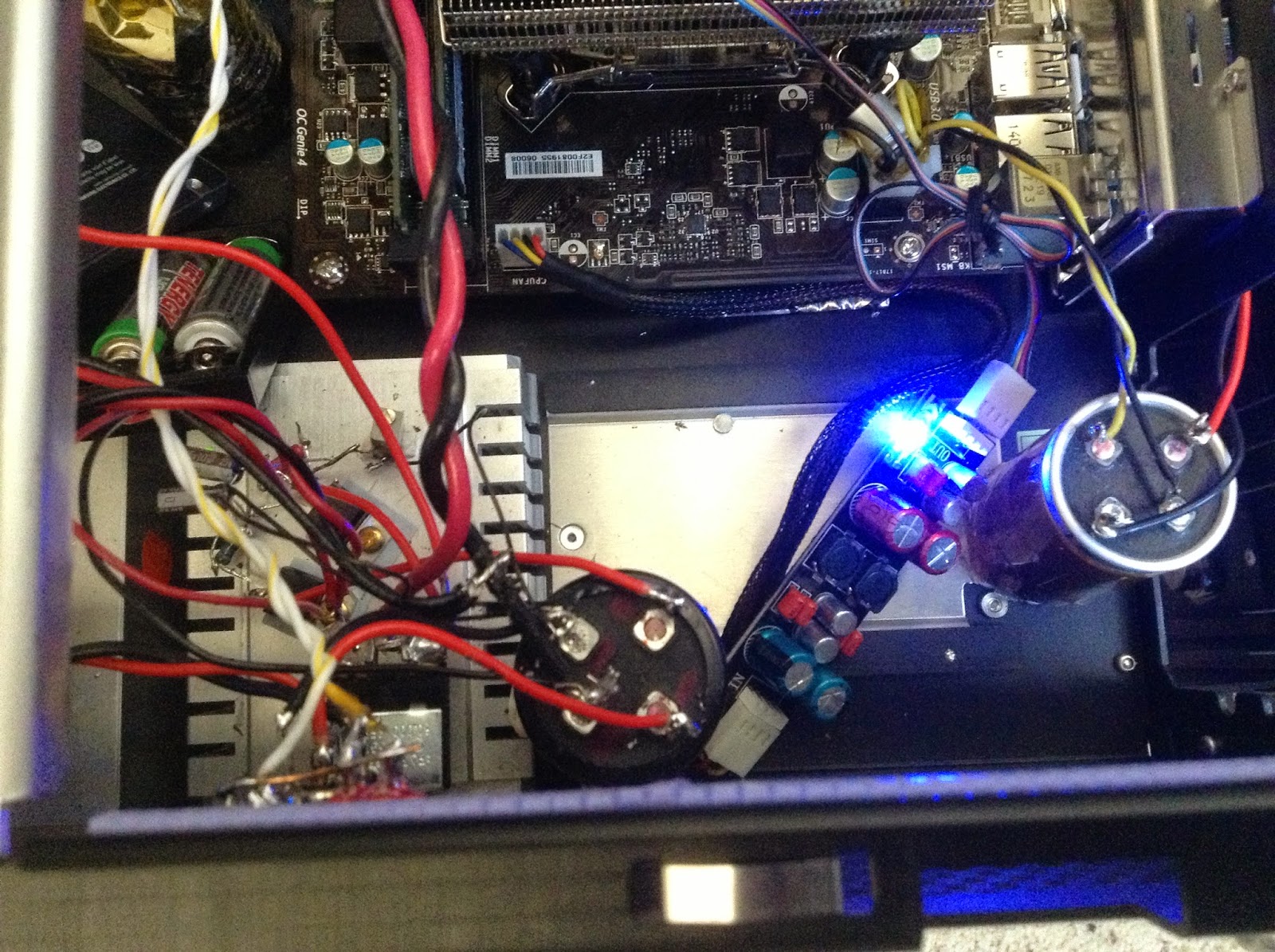
Here is the 5V reg and it's heatsink inside the chassis. The Jensen Cap on the far right is connected to the 4 pin ATX. The little board with the blue LED next to that is a fan filter, goes inline between the MB fan connector and the Scythe fan. Next to that is the Jensen which is on the input side of the regulator. And finally the heatsink with the regulator mounted on top. You can also see the two lifepo4 batteries at the top left of the heatsink.
BTW, regulators get to about 100F, around 20F over room temp, so not bad at all. So this heatsink is way overkill, but that works for me.

3.3VDC
Comments about my PC configuration:
I am using this case because I had it, and because after removing the drive bays it has lots of room to add voltage regulators and power supplies as I see fit.
The motherboard was picked because I have read that it is suitable for a DIY type linear power supply, ie not ATX compliant.
Tirnahifi thread Picoless
Processor was picked because I wanted something cheap for my new motherboard.
I had the SRAM and Scythe from my previous PC, as well as the SSD's.
Power supply - Linear picoless
Before I get into this long section, I wanted to say that if you are not brave enough to go full picoless, there was a substantial gain with one Astron RS-12A. This was the first configuration I made, I used the Astron to power a 12VDC input Pico, and also to power the 4 pin ATX as described below.
Also, you shouldn't need that much current/power, probably not as much as you think.
Voltage measured design for
So now on to the full story. I am using two Astron RS-12A (just got a 2nd one). Both Astron’s are adjusted to a little over 12V, around 12.2VDC. You need to adjust per this:
Adjust as Astron for 12VDC
Also, you shouldn't need that much current/power, probably not as much as you think.
Voltage measured design for
- 5 VDC 1.2A 2A
- 3.3VDC .6 1A
- 12VDC(4 pin) 2.2A 3 or 4A note: during playback only 1A measured.
- 12VDC(mb) .75A 1.5A
So now on to the full story. I am using two Astron RS-12A (just got a 2nd one). Both Astron’s are adjusted to a little over 12V, around 12.2VDC. You need to adjust per this:
Adjust as Astron for 12VDC
One Astron is connected to a 10,000uf, 63V Jensen 4 pole cap. With a 4 pole cap, there are two connections for input, and two for output. The input goes to the Aston, and the output goes the the 4 pin ATX connector on the motherboard. I cut off the 4 pin ATX connector from an old PC PS to use for this.
Notice that as much as possible, wires are twisted together.
Capacitor note: I used a bunch of Jensen's because I had them, bought them over the years for various now retired projects. They are great caps, but I don't know if I would go buy a bunch for a PC project. I was just looking at the cost of putting a bunch of organic polymer or Elna Silmics in parallel, but I would use 16V caps for a 12V line, so the biggest value is 1000 uf, you would need to get what I used, and that would cost around $20.
I also added a 330uf Oscon on the wires right next to the motherboard. I did this just because I have a stash of oscons, and figured it couldn’t hurt.
2nd Astron powers the 12V into the 20 pin ATX cable. The cable can be either a 20 or 24 pin ATX cable, I am using as a 20 pin cable even though my motherboard supports a 24 pin cable. The 4 extra pins are to support more current/power, but I don’t use much power so I don’t need the pins.
I cut the 12V wire (pin 10), and one ground wire. Then I connected the motherboard side of the cut wire to another 10,000uf, 63V Jensen 4 pole cap, and that goes to the 2nd Astron PS.
The Jensen is under the yellow tape, which I added for safety against shorts.
As you can see in the picture, I was still using a pico at this point. And as I said before, PC sounds nice with the pico and one or two Astron's. With one Astron, it gets a little warm.
I will try combining the Astron's at some point, to see if I can only use one Astron without sacrificing sound quality.
+5VDC
Now for 5V. I decided to make a 5VDC linear supply using an unregulated walwart,
Triad WDU9-2300. It outputs 9VDC
at 2.3A.
This walwart is not the optimal solution. I could make something nicer with a Rcore transformer, a diode bridge and some nice caps, and maybe an inductor to make a pi filter, but that is more work, and would cost more money. And there are liability concerns. With this, I just need to add a DC jack to my PC, and then add a linear reg into my PC. BTW, I may make a nice power supply like this in the future, we’ll see.
So I have a DC jack on the PC to feed in the 9VDC, its
closer to 10V under the load I have, around 1A. I feed the 9VDC into a Jensen 4 pole, and then to the
regulator. It is a 2 stage
regulator, with a pre-regulator who provides a constant voltage to the final
regulator. It also takes some of
the power/heat.
The regulator was one I had built for a previous project,
that got transplanted. It is based
on this article
I mounted the two 317’s on a good size heat sink so I
wouldn’t have to worry about over-heating. I have a bunch of heat sinks I have collected, which helps
on projects like this.
 Here is the heat sink with the regulators mounted on it. I tapped holes directly in the heatsink so I can just screw into the heatsink to hold the regulators down. The extra hole is where I broke my tap, so I had to tap another hole with a 6-32 screw, instead of the 4-40 I used in the first regulator.

Even though I broke a tap, I recommend picking up a tap set and learning to tap holes. It's not hard after you learn, just be gentle, when it gets too hard to turn back out the tap and clean out all the little metal chips. I'm sure there are videos to show how to do it online.
Here you can see how big the heatsink is. I added some caps to the circuit, but that was after this picture was taken. Caps are on the output of each reg, and on the adjust pin of the 2nd reg.
The regs are mounted with a blue thermal pad to isolate from the heatsink, and a shoulder washer under the screw, same reason. If the tab is not ground, you need to do this. I have a bunch of insulators and shoulder washers I bought a while back. After mounting, make sure the screw is isolated from the tab with a meter. One of mine was shorted, and I had to redo with another washer. Only happened because I was using a #6 screw, which is really too large. With a 6, you need to apply a fair amount of pressure to get the screw through the shoulder washer, with a 4 it just slides in.
So then I connected the input power to the reg, but did not
connect the output to the PC. I
powered it up, and nothing. Found
a bad pot, so I replaced it, and bingo, power. Adjust pot to get 5VDC, looking good.
Even though I broke a tap, I recommend picking up a tap set and learning to tap holes. It's not hard after you learn, just be gentle, when it gets too hard to turn back out the tap and clean out all the little metal chips. I'm sure there are videos to show how to do it online.
Here you can see how big the heatsink is. I added some caps to the circuit, but that was after this picture was taken. Caps are on the output of each reg, and on the adjust pin of the 2nd reg.
The regs are mounted with a blue thermal pad to isolate from the heatsink, and a shoulder washer under the screw, same reason. If the tab is not ground, you need to do this. I have a bunch of insulators and shoulder washers I bought a while back. After mounting, make sure the screw is isolated from the tab with a meter. One of mine was shorted, and I had to redo with another washer. Only happened because I was using a #6 screw, which is really too large. With a 6, you need to apply a fair amount of pressure to get the screw through the shoulder washer, with a 4 it just slides in.
Then I found a 7 ohm, 10 watt resistor in my junk draw. Hooked it up on the output of the reg,
and let it run for a while, just to make sure my reg could handle the load. I highly recommend testing the regulator under a load like this.
Before installing the heatsinks in the PC, I drilled some holes to allow airflow past the heatsinks. The holes get covered by the heatsinks.
So now I cut the wires to disconnect 5V from the Pico, as well as a few ground wires. I put in a 10,000 uf Jensen next to the PC motherboard. The 5V and ground wires get connected to the Jensen, and the other side of the Jensen is connected to the output of the regulator, through a switch.
Connect everything up, turn on all the switches, and bios
boots up, yeah. Then I shut down,
and hook up my SSD. Boot up again,
bios boots, things start to happen, and then it resets. I tried a bunch of times, and it always resets 30-60 seconds
into boot. I am depressed, and
take a break.
I reconnect the pico, and it boots fine, so PC is still
good. Reconnect my linear, and
start measuring voltages with my meter. Right before it resets, it appears the voltage may be
drooping. Hard to tell with a
meter, but I look at a few resets and see the voltage drop right before the
reset. So I theorize that the 5V
demand changes a lot during boot up, and my regulator is too slow, so 5V drops
too low and the PC resets.
Now what to do?
I bought some Lifepo4 batteries but had not used them yet. Some people swear by them for
digital. They are charged to
around 3.3 volts. Put two in
series, find some power resistors, and make a 20 ohm load
(I think). Discharge down to 4.5
volts (I didn’t pay attention). By
the next day they were back up to 5.5V, so I discharged some more, till they
were around 5.1V. My reg was set
to output 5.1V also.
I changed out the 5V switch to a double pole type. On the “output” of the switch, I
shorted the poles and that is connected to the Jensen and then the 5V into the
motherboard. On the input of the
switch, one pole goes to the 5V regulator output, and one pole goes to the
battery.
Turn everything on, and it boots up fine. The battery ensures that the 5V does
not drop too low. Also, since the
battery gets connected to the 5V regulator when the switch is on, it will keep
the battery charged to 5.1V, the output of the regulator.
I am going to play with
different 5V regulators, but am happy this works. So I think if I had a a better regulator I wouldn't need the batteries. But the battery solution was pretty easy to add, it it works fine with the batteries and my regulator.
So far, I have connected linears for the +12V and the +5V
lines on the ATX connector. There is another signal “+5 V standby” or
+5VSB on pin 9, it’s a purple wire.
I cut this, and connected it to the +5 VDC output from my linear
reg. Remember, +5 to the ATX on
the red wires goes through a switch.
Since I connected +5VSB to the output of the linear reg, it is not switched and is always on.
The last thing I did was +5 was to modify a couple SSD power
connectors. I connected these to
the switched +5, so the SSD’s get
power when the switch is on. I’ll
upgrade these later too, but for now it works.
Here is the 5V reg and it's heatsink inside the chassis. The Jensen Cap on the far right is connected to the 4 pin ATX. The little board with the blue LED next to that is a fan filter, goes inline between the MB fan connector and the Scythe fan. Next to that is the Jensen which is on the input side of the regulator. And finally the heatsink with the regulator mounted on top. You can also see the two lifepo4 batteries at the top left of the heatsink.
BTW, regulators get to about 100F, around 20F over room temp, so not bad at all. So this heatsink is way overkill, but that works for me.
3.3VDC
Now it was time for the +3.3 V linear supply. I bought one of these, Stancor STA-5760
6V@2A unregulated walwart. The Stancor has + on the outside of the jack, which is the opposite polarity that I wanted. So, I cut the cable in the middle, and then I separated the wires all the way back to the jack and walwart, and twisted the wires. I spliced them back together, but swapped the wires so + is on the inside pin.
I built a regulator with a LT1764 and a LT1587. The LT1764 drops the voltage down to around 5.2VDC, to feed the 1587 a constant voltage. The 1587 generates 3.3VDC.
I built a regulator with a LT1764 and a LT1587. The LT1764 drops the voltage down to around 5.2VDC, to feed the 1587 a constant voltage. The 1587 generates 3.3VDC.
I built up the LT1587 circuit first, to make sure it worked
right. I found a 5VDC walwart, and
used that for the input voltage to it.
I built using fixed resistors, and my first attempt was too high, 2nd
was too low , and 3rd was just right J. I used a 110 ohm (really two 220 ohms
in parallel) and a 177 ohm, should
have been 3.16V, but it was right a 3.3VDC. So if you want to build with fixed resistors you need to
have spare resistors around to tweak the value, and wait until you get it right
before soldering for real.
With the that working, I added a LT1765 in front of
that. At first, my voltage was too
high. Then I figured out it wasn’t
working because I didn’t add an output cap. I added 100uf solid poly caps (oscon type) on the outputs of
both regs, and everything worked fine.
I used a 1k and a 3.3k resistor here, get around 5.2VDC.
I also added two more caps, 10uf caps between adjust and
ground. Also added a protection diode from input to output on each reg, and a LED to indicate if 3.3V is on.
I tested with no load, and then with a 7 ohm power resistor. Worked fine under load, so I’m ready for installation. In the PC, I have a DC power jack connected to a 10,000 uf Jensen, feeding my voltage reg. The voltage reg output goes to a switch. Then it feeds another 10,000uf Jensen, which is right by the motherboard ATX connector. The ATX 3.3V wires connect to the motherboard.

I tested with no load, and then with a 7 ohm power resistor. Worked fine under load, so I’m ready for installation. In the PC, I have a DC power jack connected to a 10,000 uf Jensen, feeding my voltage reg. The voltage reg output goes to a switch. Then it feeds another 10,000uf Jensen, which is right by the motherboard ATX connector. The ATX 3.3V wires connect to the motherboard.
Connect everything, turn it on, and nothing. Let me try again, success J. My power on sequence is complicated,
first turn on walwart that powers my PCI-USB card, then +5, then turn on both
Astrons, then turn on +3 then +12 to the motherboard. With this sequence, it works fine.
And the final thing (for now). I cut the remaining wires to the pico desoldered any wires
that were still connected and removed it.
Turned back on, and it still works fine.

Here is the MB PS ATX connector after removing the Pico. I have a three Jensens here, on 12V, 5V and 3.3V.
So now I have a picoless, linear powered PC.
Here is the MB PS ATX connector after removing the Pico. I have a three Jensens here, on 12V, 5V and 3.3V.
So now I have a picoless, linear powered PC.
BTW, I think we could make this project even simpler. You could get away with a fixed voltage 3.3V reg for sure, and probably a fixed 5V reg. That would only take a few parts to implement, with the walwarts, jacks and switches and a few caps and diodes.
My power up sequence is
plug in 5V and 3.3V and 12VDC jacks
Turn on +5V switch
Turn on Astron's (note that this turns on the 12VDC 4 pin ATX connector)
Turn on 3.3V switch
Turn on 12V switch (12V to motherboard)
Hit PC on button
Part 2, modding a PCIE to USB card is here
http://randytsuch-audio.blogspot.com/2014/09/modding-silverstone-pcie-usb-card.html
![]()