Monday, November 30, 2015
Audio PC 2015
NOTE: This page was out of date, but I added some pics and information, and it's now pretty up to date with my PC, especially for implementation of the power supply and lifepo4 batteries.
PC Components
Case Lian Li PC-C34F
http://www.newegg.com/Product/Product.aspx?Item=N82E16811112229&nm_mc=TEMC-RMA-Approvel&cm_mmc=TEMC-RMA-Approvel-_-Content-_-text-_-
PC Components
Case Lian Li PC-C34F
http://www.newegg.com/Product/Product.aspx?Item=N82E16811112229&nm_mc=TEMC-RMA-Approvel&cm_mmc=TEMC-RMA-Approvel-_-Content-_-text-_-
Removed optical disk cage from right side (when facing the front of chassis) and disconnected/removed all chassis fans.
Motherboard MSI H81M-P33
H81M-P33
H81M-P33
Processor g620 pentium
i3-4130t ??
Move to another PC for different project: Xeon E3-1225 V3 3.2GHz 8M cache LGA1150 $170
i3-4130t ??
Move to another PC for different project: Xeon E3-1225 V3 3.2GHz 8M cache LGA1150 $170
Scythe shuriken rev b heatsink
DRAM
Power supply Astron +12 and DIY +5 and +3.3 Power supplies
Storage Samsung SSD 240gb drive for music files
Storage Samsung SSD 64GB drive for OS
Comments about my PC configuration:
I am using this case because I had it, and because after removing the drive bays it has lots of room to add voltage regulators and power supplies as I see fit.
The motherboard was picked because I have read that it is suitable for a DIY type linear power supply, ie not ATX compliant.
Tirnahifi thread Picoless
So now on to the full story. I am using one Astron RS-12A. I have two, but didn't think the 2nd really made a difference. However, I use the 2nd one when I connect a optical drive to this PC, the 2nd one provides 12VDC for the optical drive. Both Astron’s are adjusted to a little over 12V, around 12.2VDC. You need to adjust per this: Adjust as Astron for 12VDC

One Astron is connected to a 10,000uf, 63V Jensen 4 pole cap. With a 4 pole cap, there are two connections for input, and two for output. The input goes to the Aston, and the output goes the the 4 pin ATX connector on the motherboard. I cut off the 4 pin ATX connector from an old PC PS to use for this.
Notice that as much as possible, wires are twisted together.

I also added a 330uf Oscon on the wires right next to the motherboard. I did this just because I have a stash of oscons, and figured it couldn’t hurt.
The Astron also powers the 12V into the 20 pin ATX cable. The cable can be either a 20 or 24 pin ATX cable, I am using as a 20 pin cable even though my motherboard supports a 24 pin cable. The 4 extra pins are to support more current/power, but I don’t use much power so I don’t need the pins.


I cut the 12V wire (pin 10), and one ground wire. Then I connected the motherboard side of the cut wire to another 10,000uf, 63V Jensen 4 pole cap, and that goes to the Astron PS.
The Jensen is under the yellow tape, which I added for safety against shorts.
This walwart is not the optimal solution. I could make something nicer with a Rcore transformer, a diode bridge and some nice caps, and maybe an inductor to make a pi filter, but that is more work, and would cost more money. And there are liability concerns. With this, I just need to add a DC jack to my PC, and then add a linear reg into my PC.

Before installing the heatsinks in the PC, I drilled some holes to allow airflow past the heatsinks. The holes get covered by the heatsinks.
So now I cut the wires to disconnect 5V from the Pico, as well as a few ground wires. I put in a 10,000 uf Jensen next to the PC motherboard. The 5V and ground wires get connected to the Jensen, and the other side of the Jensen is connected to the output of the regulator, through a switch.
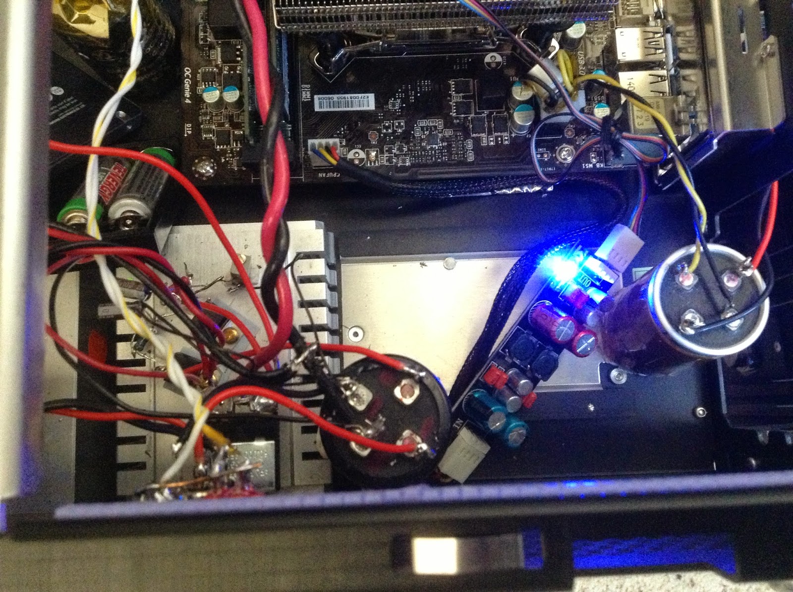
Here is the 5V reg and it's heatsink inside the chassis. The Jensen Cap on the far right is connected to the 4 pin ATX. The little board with the blue LED next to that is a fan filter, goes inline between the MB fan connector and the Scythe fan. Next to that is the Jensen which is on the input side of the regulator. And finally the heatsink with the regulator mounted on top. You can also see the two lifepo4 batteries at the top left of the heatsink.
BTW, regulators get to about 100F, around 20F over room temp, so not bad at all. So this heatsink is way overkill, but that works for me.

Dec, 2015 EDIT:
I've made some other changes that I wanted to add to my blog.
Here is a newer pic of my 5V circuit.

The significant changes is I changed to use much larger lifepo4 batteries.
I've been using these batteries
26650 clone lifepo4s
To get 5V out of lifepo4s, connect two up, with the positive of one connected to the negative of the 2nd. Now you'll see about 6.6V across the batteries. Then I put a small value power resistor to drain the batteries. It took a while, and when you remove the load, the voltage will creep back up, so you may need to do it a few times, and go lower than 5V. Once its a little lower than 5V, connect per the above and it should be fine.
The other significant change is that the switch in the figure above has been replaced by a relay. The relay is connected to 12V for turn on.
This same 5V supply is used to power my two SSD's. One SSD holds the OS (windows Server 2012 R2) and the other holds all my music. I plan to try making a separate 5V for the SSDs.
3.3VDC

Here is the MB PS ATX connector after removing the Pico. I have a three Jensens here, on 12V, 5V and 3.3V.
EDIT Dec 2015
Like for the 5V section above, I'm using these batteries. 3.3 is easy, just takes one at normal charge.
26650 clone lifepo4s
And the switch has been replaced by a relay. The relay is connected to 12V for turn on.

So now I have a picoless, linear powered PC.
Comments about my PC configuration:
I am using this case because I had it, and because after removing the drive bays it has lots of room to add voltage regulators and power supplies as I see fit.
The motherboard was picked because I have read that it is suitable for a DIY type linear power supply, ie not ATX compliant.
Tirnahifi thread Picoless
Power supply - Linear and LIFEPO4
So now on to the full story. I am using one Astron RS-12A. I have two, but didn't think the 2nd really made a difference. However, I use the 2nd one when I connect a optical drive to this PC, the 2nd one provides 12VDC for the optical drive. Both Astron’s are adjusted to a little over 12V, around 12.2VDC. You need to adjust per this: Adjust as Astron for 12VDC
One Astron is connected to a 10,000uf, 63V Jensen 4 pole cap. With a 4 pole cap, there are two connections for input, and two for output. The input goes to the Aston, and the output goes the the 4 pin ATX connector on the motherboard. I cut off the 4 pin ATX connector from an old PC PS to use for this.
Notice that as much as possible, wires are twisted together.
I also added a 330uf Oscon on the wires right next to the motherboard. I did this just because I have a stash of oscons, and figured it couldn’t hurt.
The Astron also powers the 12V into the 20 pin ATX cable. The cable can be either a 20 or 24 pin ATX cable, I am using as a 20 pin cable even though my motherboard supports a 24 pin cable. The 4 extra pins are to support more current/power, but I don’t use much power so I don’t need the pins.
I cut the 12V wire (pin 10), and one ground wire. Then I connected the motherboard side of the cut wire to another 10,000uf, 63V Jensen 4 pole cap, and that goes to the Astron PS.
The Jensen is under the yellow tape, which I added for safety against shorts.
+5VDC
Now for 5V. I decided to make a 5VDC linear supply using an unregulated walwart, Triad WDU9-2300. It outputs 9VDC at 2.3A.
This walwart is not the optimal solution. I could make something nicer with a Rcore transformer, a diode bridge and some nice caps, and maybe an inductor to make a pi filter, but that is more work, and would cost more money. And there are liability concerns. With this, I just need to add a DC jack to my PC, and then add a linear reg into my PC.
So I have a DC jack on the PC to feed in the 9VDC, its closer to 10V under the load I have, around 1A. I feed the 9VDC into a Jensen 4 pole, and then to the regulator. It is a 2 stage regulator, with a pre-regulator who provides a constant voltage to the final regulator. It also takes some of the power/heat.
The regulator was one I had built for a previous project, that got transplanted. It is based on this article
I mounted the two 317’s on a good size heat sink so I wouldn’t have to worry about over-heating. I have a bunch of heat sinks I have collected, which helps on projects like this.
 Here is the heat sink with the regulators mounted on it. I tapped holes directly in the heatsink so I can just screw into the heatsink to hold the regulators down. The extra hole is where I broke my tap, so I had to tap another hole with a 6-32 screw, instead of the 4-40 I used in the first regulator.

Even though I broke a tap, I recommend picking up a tap set and learning to tap holes. It's not hard after you learn, just be gentle, when it gets too hard to turn back out the tap and clean out all the little metal chips. I'm sure there are videos to show how to do it online.
Here you can see how big the heatsink is. I added some caps to the circuit, but that was after this picture was taken. Caps are on the output of each reg, and on the adjust pin of the 2nd reg.
The regs are mounted with a blue thermal pad to isolate from the heatsink, and a shoulder washer under the screw, same reason. If the tab is not ground, you need to do this. I have a bunch of insulators and shoulder washers I bought a while back. After mounting, make sure the screw is isolated from the tab with a meter. One of mine was shorted, and I had to redo with another washer. Only happened because I was using a #6 screw, which is really too large. With a 6, you need to apply a fair amount of pressure to get the screw through the shoulder washer, with a 4 it just slides in.
So then I connected the input power to the reg, but did not connect the output to the PC. I powered it up, and nothing. Found a bad pot, so I replaced it, and bingo, power. Adjust pot to get 5VDC, looking good.
Even though I broke a tap, I recommend picking up a tap set and learning to tap holes. It's not hard after you learn, just be gentle, when it gets too hard to turn back out the tap and clean out all the little metal chips. I'm sure there are videos to show how to do it online.
Here you can see how big the heatsink is. I added some caps to the circuit, but that was after this picture was taken. Caps are on the output of each reg, and on the adjust pin of the 2nd reg.
The regs are mounted with a blue thermal pad to isolate from the heatsink, and a shoulder washer under the screw, same reason. If the tab is not ground, you need to do this. I have a bunch of insulators and shoulder washers I bought a while back. After mounting, make sure the screw is isolated from the tab with a meter. One of mine was shorted, and I had to redo with another washer. Only happened because I was using a #6 screw, which is really too large. With a 6, you need to apply a fair amount of pressure to get the screw through the shoulder washer, with a 4 it just slides in.
Then I found a 7 ohm, 10 watt resistor in my junk draw. Hooked it up on the output of the reg, and let it run for a while, just to make sure my reg could handle the load. I highly recommend testing the regulator under a load like this.
Before installing the heatsinks in the PC, I drilled some holes to allow airflow past the heatsinks. The holes get covered by the heatsinks.
So now I cut the wires to disconnect 5V from the Pico, as well as a few ground wires. I put in a 10,000 uf Jensen next to the PC motherboard. The 5V and ground wires get connected to the Jensen, and the other side of the Jensen is connected to the output of the regulator, through a switch.
Connect everything up, turn on all the switches, and bios boots up, yeah. Then I shut down, and hook up my SSD. Boot up again, bios boots, things start to happen, and then it resets. I tried a bunch of times, and it always resets 30-60 seconds into boot. I am depressed, and take a break.
I reconnect the pico, and it boots fine, so PC is still good. Reconnect my linear, and start measuring voltages with my meter. Right before it resets, it appears the voltage may be drooping. Hard to tell with a meter, but I look at a few resets and see the voltage drop right before the reset. So I theorize that the 5V demand changes a lot during boot up, and my regulator is too slow, so 5V drops too low and the PC resets.
Now what to do? I bought some Lifepo4 batteries but had not used them yet. Some people swear by them for digital. They are charged to around 3.3 volts. Put two in series, find some power resistors, and make a 20 ohm load (I think). Discharge down to 4.5 volts (I didn’t pay attention). By the next day they were back up to 5.5V, so I discharged some more, till they were around 5.1V. My reg was set to output 5.1V also.
I changed out the 5V switch to a double pole type. On the “output” of the switch, I shorted the poles and that is connected to the Jensen and then the 5V into the motherboard. On the input of the switch, one pole goes to the 5V regulator output, and one pole goes to the battery.
Turn everything on, and it boots up fine. The battery ensures that the 5V does not drop too low. Also, since the battery gets connected to the 5V regulator when the switch is on, it will keep the battery charged to 5.1V, the output of the regulator.
I am going to play with different 5V regulators, but am happy this works. So I think if I had a a better regulator I wouldn't need the batteries. But the battery solution was pretty easy to add, it it works fine with the batteries and my regulator.
So far, I have connected linears for the +12V and the +5V lines on the ATX connector. There is another signal “+5 V standby” or +5VSB on pin 9, it’s a purple wire. I cut this, and connected it to the +5 VDC output from my linear reg. Remember, +5 to the ATX on the red wires goes through a switch. Since I connected +5VSB to the output of the linear reg, it is not switched and is always on.
The last thing I did was +5 was to modify a couple SSD power connectors. I connected these to the switched +5, so the SSD’s get power when the switch is on. I’ll upgrade these later too, but for now it works.
Here is the 5V reg and it's heatsink inside the chassis. The Jensen Cap on the far right is connected to the 4 pin ATX. The little board with the blue LED next to that is a fan filter, goes inline between the MB fan connector and the Scythe fan. Next to that is the Jensen which is on the input side of the regulator. And finally the heatsink with the regulator mounted on top. You can also see the two lifepo4 batteries at the top left of the heatsink.
BTW, regulators get to about 100F, around 20F over room temp, so not bad at all. So this heatsink is way overkill, but that works for me.
Dec, 2015 EDIT:
I've made some other changes that I wanted to add to my blog.
Here is a newer pic of my 5V circuit.

The significant changes is I changed to use much larger lifepo4 batteries.
I've been using these batteries
26650 clone lifepo4s
The other significant change is that the switch in the figure above has been replaced by a relay. The relay is connected to 12V for turn on.
This same 5V supply is used to power my two SSD's. One SSD holds the OS (windows Server 2012 R2) and the other holds all my music. I plan to try making a separate 5V for the SSDs.
3.3VDC
Now it was time for the +3.3 V linear supply. I bought one of these, Stancor STA-5760 6V@2A unregulated walwart. The Stancor has + on the outside of the jack, which is the opposite polarity that I wanted. So, I cut the cable in the middle, and then I separated the wires all the way back to the jack and walwart, and twisted the wires. I spliced them back together, but swapped the wires so + is on the inside pin.
I built a regulator with a LT1764 and a LT1587. The LT1764 drops the voltage down to around 5.2VDC, to feed the 1587 a constant voltage. The 1587 generates 3.3VDC.
I built a regulator with a LT1764 and a LT1587. The LT1764 drops the voltage down to around 5.2VDC, to feed the 1587 a constant voltage. The 1587 generates 3.3VDC.
I built up the LT1587 circuit first, to make sure it worked right. I found a 5VDC walwart, and used that for the input voltage to it. I built using fixed resistors, and my first attempt was too high, 2nd was too low , and 3rd was just right J. I used a 110 ohm (really two 220 ohms in parallel) and a 177 ohm, should have been 3.16V, but it was right a 3.3VDC. So if you want to build with fixed resistors you need to have spare resistors around to tweak the value, and wait until you get it right before soldering for real.
With the that working, I added a LT1765 in front of that. At first, my voltage was too high. Then I figured out it wasn’t working because I didn’t add an output cap. I added 100uf solid poly caps (oscon type) on the outputs of both regs, and everything worked fine. I used a 1k and a 3.3k resistor here, get around 5.2VDC.
I also added two more caps, 10uf caps between adjust and ground. Also added a protection diode from input to output on each reg, and a LED to indicate if 3.3V is on.
I tested with no load, and then with a 7 ohm power resistor. Worked fine under load, so I’m ready for installation. In the PC, I have a DC power jack connected to a 10,000 uf Jensen, feeding my voltage reg. The voltage reg output goes to a switch. Then it feeds another 10,000uf Jensen, which is right by the motherboard ATX connector. The ATX 3.3V wires connect to the motherboard.

NOTE on diagram
I tested with no load, and then with a 7 ohm power resistor. Worked fine under load, so I’m ready for installation. In the PC, I have a DC power jack connected to a 10,000 uf Jensen, feeding my voltage reg. The voltage reg output goes to a switch. Then it feeds another 10,000uf Jensen, which is right by the motherboard ATX connector. The ATX 3.3V wires connect to the motherboard.
This circuit diagram has a mistake at the switch. The two poles at the output should be shorted together. So when the switch is closed, both the battery and the 3.3V regulator output are connected to the Jensen 4 pole and then the PC 3.3V input.
Connect everything, turn it on, and nothing. Let me try again, success J.
Here is the MB PS ATX connector after removing the Pico. I have a three Jensens here, on 12V, 5V and 3.3V.
EDIT Dec 2015
Like for the 5V section above, I'm using these batteries. 3.3 is easy, just takes one at normal charge.
26650 clone lifepo4s
And the switch has been replaced by a relay. The relay is connected to 12V for turn on.

BTW, with the batteries in place, a simple 3.3V and 5V reg should work just as good as the ones I used for this.
Relays for power control
So I would have to turn on a bunch of switches, and worry about the sequence to turn on power, I used relays instead.
I use 12V double pole, double throw relays. The relay coil is connected to the output of the astron 12V power supply. So, when I turn on the 12V power, all of the relays turn on, and power up the PC. I leave the 5V and 3.3V regs powered all the time. I also added a relay to provide 3.3V power to my silverstone USB card, which is modded per the description below.
I used these relays because they were on sale at the time
12v dc 10a dpdt relay Radio Shack
Part 2, modding a PCIE to USB card is here
http://randytsuch-audio.blogspot.com/2014/09/modding-silverstone-pcie-usb-card.html
Sunday, November 29, 2015
Soekris R2R Dam Dac - Modding
Mods I made
Summary
Thought it would be good to rate the mods below
Biggest one is changing the reference voltage to the shift registers. That is one of the more complicated changes, but it makes a big difference.
Next was using battery power for the front end, either the amanero or exD card and for isolated 3.3. For some reason, this made a big improvement.
3.3V is next, and 1.2V is last.
At least that is my current rating of the main changes I made. As always YMMV.
Links
tirnahifi dac thread
Most of the mods are from this thread. Its where I got the ideas for what is presented below.
NOTE on Batteries
For the mods described below, I'm using these batteries
batteryspace 26650 lifepo4 clone
This is a clone of the 26650 lifepo4 cell. They have worked well for me.
They are easy to use, and easy to charge. To charge, you just need to provide them with around 3.3VDC, regulated. I've charged as high as 3.6V, and as low as 2.5V. 2.5 volt is using two in series to generate 5vdc. I did this in my PC.
For some of the cells, I add a small value, 1W resister, to current limit between the charger and the battery. I used 1.5 ohm resistors, will describe where later.
These types of batteries can draw a lot of charging current, and you do not want to provide too much current. But if you keep them charged all the time, or at least close to full charge, this really is not an issue. I haven't decided yet if it matters if I apply the battery charging voltage when I listen to the DAC.
MODs
Remove output opamps
Remove output opamps
Removed the 4 output opamps on middle of photo below. U28, 29, 31 and 32. As you can see U29 and U32 have thermal pads underneath. You may have to heat up the body of the parts to remove them.
EDIT: Need to mention another part to remove, two really, C135 and C143. In the picture below, they were already removed, the purple wires pass right by them. They caps are on the output, as part of a high frequency filter, but I think they hurt the sound. If you think you need high frequency filtering, I would add a high quality, small value film cap from each output to ground. I didn't find a need to add a cap here.
EDIT: Need to mention another part to remove, two really, C135 and C143. In the picture below, they were already removed, the purple wires pass right by them. They caps are on the output, as part of a high frequency filter, but I think they hurt the sound. If you think you need high frequency filtering, I would add a high quality, small value film cap from each output to ground. I didn't find a need to add a cap here.

I only use the raw output, so I don't need these opamps. And these are the only parts that use "PWR A+" and "PWR A-". This makes modding the power section of the DAC easier, and you can run the DAC from a lower voltage.
New Reference Voltage to Shift Registers
The reference voltage used to power the 4 rows of shift registers is crucial to getting good sound from this DAC. There are many mods out there associated with improving the opamp circuit used to generate +/-4VDC to power the shift registers.
But I went a different route, I supplied +3.3V and -3.3V from LIFEPO4 cells to power the shift registers. They run fine on this voltage, and the dac sounds really good using lifepo4 batteries here.
But I went a different route, I supplied +3.3V and -3.3V from LIFEPO4 cells to power the shift registers. They run fine on this voltage, and the dac sounds really good using lifepo4 batteries here.
The first and third row of shift registers get negative power. In my pictures, purple is negative 3.3V, and orange is positive 3.3V. For the shift register chip, pin 8 is ground (last pin on the pin 1 side) and pin 16 is VCC. Pin 16 is opposite pin 1.
So, on the first row, the +3.3 ends up on pin 16 for all the shift registers on rows 1 and 3.
Row 2 and 4 get -3.3VDC. For these shift registers, ground is on pin 16 (VCC), and -3.3 is on pin 8 (gnd). So these devices see +3.3 from ground to VCC, but they are really running at -3.3V.
I ended up removing a few passives around each op amp and the opamp itself. You can see this in the picture above. With the opamp, I heard some distortion that went away when the opamp is removed.
Initially, I wired the + and -3.3VDC to a cap next to the op amp with a small wire. Wire goes directly to a switch. Purple/grey wires are -3.3VDC, and orange are +3.3VDC. You can see this in the pictures below.

In the picture below, the opamps are still installed. Compare to the picture above, where they have been removed.

Later, I changed the wiring, to wire +/- 3.3V to each shift register, so I have 16 wires, 8 for positive and 8 for negative. I wired a couple directly to the shift register, but I was making solder bridges, so the rest I soldered the wire to a cap next to the shift register, which is much easier.


And it does sound better with the 16 wires versus 4, more detail and better instrument separation.
Initially, I wired the + and -3.3VDC to a cap next to the op amp with a small wire. Wire goes directly to a switch. Purple/grey wires are -3.3VDC, and orange are +3.3VDC. You can see this in the pictures below.
In the picture below, the opamps are still installed. Compare to the picture above, where they have been removed.

Later, I changed the wiring, to wire +/- 3.3V to each shift register, so I have 16 wires, 8 for positive and 8 for negative. I wired a couple directly to the shift register, but I was making solder bridges, so the rest I soldered the wire to a cap next to the shift register, which is much easier.


And it does sound better with the 16 wires versus 4, more detail and better instrument separation.
To charge the batteires, I used an old, Twisted Pear dual regulator laying around. I set both sides for 3.4VDC. It needs AC, I used two walwarts that supply about 12VAC each to the dual regulator. Charging power is applied through another switch.
Figure of battery and switch connections.
 |
| FIGURE Batteries Charger and switch connections |
Here is a picture of the two batteries that supply the voltage to the shift registers. I used some copper tape to connect the battery return to ground on the dac. Copper tape creates a good, low impedance path because it has lots of surface area. The twisted pear dual reg is at the top of the picture.
The two switches control the charging voltage for the lifepo4 batteries. The switch on the left turns on charging voltage to the shift register batteries. The one on the right turns on the charging voltage to the 3.3V and 1.2V batteries described below.
At some point in the future, I may redo this section, and make the battery ground shorter by moving the batteries over a bit.

Relays for the power switching
I also decided to use relays to control power to the dac. Went to my local Frys, and picked up two of these 4 pole relays.
4 pole dt relay


+V in is only used, now it supplies the 3.3V linear reg, and the 1.2V switcher.

3.3VDC upgrade
The dac comes with a 3.3V linear reg. This is the 3 pin device with the tab, on the right of the clock chip in the picture above. I removed it by cutting the three pins, and then heating up the tab until it came loose.
I added another lifepo4 battery, and wired it through the relay. +3.3 from the battery/relay go to the middle pin of the regulator. I soldered the - tab from the battery directly to a ground pad on the board, a pad that had been used by a cap I removed.

I also added a separate wire to VCC and ground of the clock, you can see in the the picture above. I also removed a resistor to the above, and to the left of the clock. This isolates the clock from it's other +3.3V path. This clock change had a small positive effect, but still recommended because its easy and just takes a couple of wires.
Made another 3.3 VDC regulator to charge this battery, and the one that powers the 1.2V linear reg.
It is a simple reg made from a LM317. I feed it power from an unregulated walwart.

The output of this regulator goes to a 4 pole switch. Two of the poles switch the positive output of the reg, and two poles switch the regulator ground. From the switch, one set of positive and ground wires go to the 3.3v battery.
Here is a schematic of my battery charger circuit from the picture above. The LM317 is set to 3.3VDC output.

R3 and R4 are 1.5ohm, 1W resistors intended to current limit the charging current, and to provide a little isolation between the charger and the battery while the dac is on.
1.2VDC Switcher replacement
An LT1764 linear regulator generates the 1.2VDC. This is the minimum voltage that this part can generate. I used it because I had a few on hand. As shown in the schematic above, pins 1 and 2, and 4 and 5 are shorted.
I put a short wire between these pins, close to the body of the part, and then cut off most of pin 2 and 4.
Pins 3 and 5 solder directly to the board, to J2-1 and J2-2. Soldering these to pins to the board "mounts" the LT1764 to the board.
Pin 1 in bent up, and then a wire is soldered to it from the relay. When the relay is on, 3.3V is fed to the LT1764, and it generates 1.2V to the DAC.

I tested the LT1764 stand alone first, after shorting pins 1 to 2, and 4 to 5, I connected it to 5VDC, and measured the output. The output was high, around 1.5V. I decided it needed an output cap, so I found a small cap (I think it's 47uf, but 10uf or larger would work), and soldered the cap from pin 3 (ground) to pin 5 (output). Tried again, and I now have 1.2V out of the 1764.
After checking it, I installed it on the board. With this installed, I would no longer use the 1.2V switcher, and I had already removed the 3.3V linear from the board, so I don't need to provide 12VDC to the A+ input anymore, and I removed the two wires I had connected to J1 to provide that voltage.
Powered it up, and all was good :)
Then I removed the 1.2V switcher, most of the large input caps, and the two inductors by the switcher. The inductors are difficult to removed, I broke them with pliers (ferrite is brittle) and then removed all the pieces.
It sounded slightly better after going to the 1.2V linear, and a little better after removing the old components. Not a huge change, I honestly expected more, but still worthwhile to do.
Amanero Power and isolated 3.3V power
Initially, I powered the Amanero and the isolated 3.3V with a simple LM317 reg and a 9V walwart. Sounded fine, and I didn't think this power was critical since it is isolated from the dac. I was wrong.
On advice from nige2000, I added another lifepo4 battery here, and it was a major improvement. More so than the 1.2V regulator mod, and also I think more than the 3.3V mod.

Battery grounding
As used in this mod, each battery is like a little power supply. So for grounding the battery, I tried to connect the battery ground as close as possible to the parts that the battery was powering.
So the ladder batteries are grounded relatively close to the shift registers. The 3.3V battery is connected to ground by the 3.3V parts, etc.
FPGA Cap mod
There are a bunch of caps, 36 to be exact, between the FPGA and shift registers. The caps are required because some of the shift registers are running at -3.3V, So, without the caps, the either the fpga or the shift registers would be damaged.
I'm changing the caps to 100pf panasonic film caps. Mouser and digikey both carry.
mouser link to caps
I bought a hundred because of the quantity discount it was just a little more than 50. I would order some extras because they are tiny, and easy to lose a few.
To remove the existing caps, I use two soldering irons. I recently picked up a 2nd iron from hobby king, a Hakko clone that was really cheap there
hobbyking soldering iron
If you heat up each end of a cap with an iron, it just pops out really easily.
I replaced one cap, made sure the DAC still worked, then replaced 4 (first little group), and checked again.
Then I did 5 more, for a total of 9. That is for one set of shift registers, so 1/4 of the way done, and checked again. Checking this often slows it down, but gives me piece of mind :)
To install, I add a little dab of solder to one pad, and then tack the cap down to that pad. Then I solder the other pad with a little more solder. I use tweezers to hold the cap. With this method for removal and replacement, it actually goes pretty quickly, easier than I thought it would be.
After replacing 27 of the caps, I heard a tiny bit of static in one channel. I tried to touch up some of the pads, and the tiny bit of static became a lot of noise. Pulled out the scope, and started looking at the shift register side of the caps. On a few of the caps, the signal was very low, as compared to the others. On these same caps, the signal was fine on the FPGA side.
I replaced those caps, carefully using as little heat as possible. I checked the signals again, and they were fine. Then I hooked it up, and static/noise was gone.
These film surface mount caps are very delicate, and you should use as little heat as possible to install them. You should also check them after you install them.
But, I also heard an improvement in detail, realism and low end presence after making this change, so I still recommend the change, but its a borderline recommendation, because the caps are so delicate and easy to break.
exD USB to I2S card
Got a used exD USB to I2S card to try instead of the Amanero, to see how it would sound.
I had to email exD to get drivers for Windows 2012R2, but he sent me a new driver, and with that I installed it fine.
exd audio
This card needs 9V to run, it does not use USB power. It has a few onboard regs that run off of the 9V.
There is a 5V reg, and a 3.3V reg that runs from 5V, and one around 3.1V that runs from 9V.
EDIT on March, 2018
First update in a long time lol.
Changed USB to I2S card.
Bought this one from DIYINHK
Its the
XMOS 768kHz DXD DSD512(DSD1024) high-quality USB to I2S/DSD PCB
Also wired in a Potato Semi 74G374 octal flip flop between the DIYINHK card and the DAC.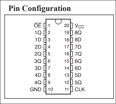
Pin 20 to 3.3V,
Pin 10 and pin 1 to ground
pin 11 to i2s master clock
pin 12 to dac data
pin 13 to xmos data
pin 14 to xmos lr clk
pin 15 to dac lr clk
pin 16 to dac bit clk
pin 17 to xmos bit clk
Pretty sure the above is correct, but I can't see the bottom silkscreen on the xmos board since it's wired up, and the xmos signal names are there.
I soldered FF into a 24 pin adapter, but its only a 20 pin device so the pin numbers are off.
The top of the adapter board, in the pic below, has pin 11 (which has a white wire in it) on the left, and pin 20 (blue wire) on the right. So, pins 1-10 are on the bottom.


I also removed two isolators, and jumpered across to make the connections, so pic below

Tuesday, November 17, 2015
Soekris R2R Dam DAC
Decided to document my build and mods for a Soekris R2R DAC.
This page contains information on how to setup the dac.
Links
Diyaudio reference dac module thread started by Soekris
web shop to buy
dimdim blog
hifiduino blog DAC user's guide
moredamfilters blog
firmware version 0.99
moredamfilters released filters
firmware version 1.04 was the latest download 1021full_104.skr to get everything
Go here to see how I modded this dac:
Modding the dac

Firmware and Filter updates
To update the filter, you need to connect a RS-232 port to this DAC, but these days most PC's don't have one. And early on, people had problems establishing a connection with different 232 adapters.. It seems there are certain adapters that work.

This page contains information on how to setup the dac.
Links
Diyaudio reference dac module thread started by Soekris
web shop to buy
dimdim blog
hifiduino blog DAC user's guide
moredamfilters blog
firmware version 0.99
moredamfilters released filters
firmware version 1.04 was the latest download 1021full_104.skr to get everything
Go here to see how I modded this dac:
Modding the dac
Startup
Power: For
quick startup, I used two walwarts that output unregulated DC of around
12V. You need at least 180 ma from the positive
supply, and 60 ma from the negative supply.
Voltage needs to be +- 7-15V DC, preferable 9-12V DC or 2x 7-8V AC. It
goes though a diode bridge so polarity doesn't matter. Connector is MTA156
type. I just soldered the wires directly
into J1, with the positive voltage to the top hole, and negative voltage to the
bottom hole.
Output: I used the raw outputs from the J7 connector. J7 is on right in figure below
Input: Used an Amanero USB to I2S board
I2S was connected with very short wires. I made little adapters by soldering pin
sockets to wires, the sockets plug into the pins of J3. J3 is left bottom in figure below.
Amanero clk goes to I2S BCLK on
J3.
Amanero fsclk goes to I2S LRCLK on
J3.
Amanero data goes to I2S data on
J3.
ground to ground
3.3v to iso 3.3v
ground to ground
3.3v to iso 3.3v
Bclk and LRCLK cross each other, kind of like a null modem
connection.

Firmware and Filter updates
To update the filter, you need to connect a RS-232 port to this DAC, but these days most PC's don't have one. And early on, people had problems establishing a connection with different 232 adapters.. It seems there are certain adapters that work.
I use a ATEN USB to Serial RS-232
Converter, Model UC-232A. I
found this one on ebay
To connect
ATEN Pin 2 goes to J10 pin 3
ATEN Pin 3 goes to
J10 pin 2
ATEN Pin 5 goes to J10 pin 5
I made a little adapter. One side of the adapter is a 9 pin female DB9 that plugs into the ATEN. Then about 6 feet of wire to make it easier to connect, and then some pin sockets that plug into the pins on the DAC.
This adapter needed drivers installed. Drivers for this adapter are here
Aten drivers
Go towards the bottom, and click Support and Download
There are drivers for Android, Linux, Mac and Windows, so pretty much anything.
I also used extraputty for my terminal program
extraputty
I looked in the windows Device Manager page to see what the serial port number was. Go to Control Panel, System then select Device Manager (this is for Windows 7)
Setup the comm port as follows:
 Select Open, and it will start a terminal session.
Turn on your DAC, and you should see some stuff on the screen.

Type "+++" (three plus signs) to enable the interface.
Type "?" to get a list of commands.
You can get Soekris firmware here
Soekris firmware
At the extraputty screen, type in
download
On the top of the extraputty screen, select Files Transfer, then Xmodem, then send
then find and select the skr file to send
You should see this screen

IMPORTANT:
When the download is complete, type
update
then y when it asks are you sure
You should see this screen now

Filters
First time I tried the dac, I had upgraded to the the firmware, and then tried old filters, and the dac didn't work. That's because you need to use 0.99 filters for 0.99 firmware, otherwise the dac won't receive data, and the led will just blink.
You can find filters here
moredamfilters latest filters EDIT: I think this link is now broken
New filter link
I downloaded the partypak.
Within the partypak, there are 4 banks of filters.
Type +++ at the extraputty screen,
Type download, and download the partypak skr file

To select the filters, in play mode you type: F4 or F5 or F6 or F7 (not the function keys!) for selecting one of the 4 filters
When you go into the uManager (+++) you type:
set filters = Linear
or
set filters = Mixed
or
set filters = Minimum
or
set filters = Soft
Linear, Mixed, Minimum, Soft corresponds to F4, F5, F6, F7
Linear selects bank 1of the filters
Mixed selects bank 2
Minimum selects bank 3
Soft selects bank 4
I set to soft, for bank 4 the new NOS filter

Type:
filters
to see the current filters selected
If you set the filter in umanager, it will remember over a power cycle, if you use F4-F7 in play mode, it will not.
I currently using the NOS filter from the partypak, and am quite happy with the sound using this filter.
Mod information is here
soekris r2r dam dac modding
Aten drivers
Go towards the bottom, and click Support and Download
There are drivers for Android, Linux, Mac and Windows, so pretty much anything.
I also used extraputty for my terminal program
extraputty
I looked in the windows Device Manager page to see what the serial port number was. Go to Control Panel, System then select Device Manager (this is for Windows 7)
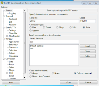
Setup the comm port as follows:
- Baud rate: 115,200 (This is pretty fast. Use a good, short cable)
- Data bits: 8
- Stop bits: 1
- Parity: none
- Flow control: none
I just had to click Serial, and put in Com3 (or whatever you com port is, and set the speed.
I also saved it as dac, so I could recall it later.

Turn on your DAC, and you should see some stuff on the screen.

Type "+++" (three plus signs) to enable the interface.
Type "?" to get a list of commands.
You can get Soekris firmware here
Soekris firmware
At the extraputty screen, type in
download
On the top of the extraputty screen, select Files Transfer, then Xmodem, then send
then find and select the skr file to send
You should see this screen

When the download is complete, type
update
then y when it asks are you sure
You should see this screen now

Filters
First time I tried the dac, I had upgraded to the the firmware, and then tried old filters, and the dac didn't work. That's because you need to use 0.99 filters for 0.99 firmware, otherwise the dac won't receive data, and the led will just blink.
You can find filters here
moredamfilters latest filters EDIT: I think this link is now broken
New filter link
I downloaded the partypak.
Within the partypak, there are 4 banks of filters.
Type +++ at the extraputty screen,
Type download, and download the partypak skr file

To select the filters, in play mode you type: F4 or F5 or F6 or F7 (not the function keys!) for selecting one of the 4 filters
When you go into the uManager (+++) you type:
set filters = Linear
or
set filters = Mixed
or
set filters = Minimum
or
set filters = Soft
Linear, Mixed, Minimum, Soft corresponds to F4, F5, F6, F7
Linear selects bank 1of the filters
Mixed selects bank 2
Minimum selects bank 3
Soft selects bank 4
I set to soft, for bank 4 the new NOS filter
Type:
filters
to see the current filters selected
If you set the filter in umanager, it will remember over a power cycle, if you use F4-F7 in play mode, it will not.
I currently using the NOS filter from the partypak, and am quite happy with the sound using this filter.
Mod information is here
soekris r2r dam dac modding
![]()