Wednesday, February 17, 2016
Running Windows from RAM
My instructions for
running Windows out of RAM, instead of a HDD or SSD.
Specifically, I used
free software and other free stuff you can download from the internet, and made
Windows Server 2012 R2 load into, and run from the ram in my PC.
These instructions were mostly performed from Windows 7.
I believe they will work
on Windows 7, 8 or 10, and maybe Vista.
One the the main utilities I used, EasyBCD will NOT run on Server 2012.
I find it nice to be
able to boot into Windows7 to do stuff non audio related, and then boot into
Server 2012 to listen to music.
FYI, it seems like you can pick up cheap licenses for windows 10 these days if you're willing to download the installation files, and make you own bootable USB installation stick..
FYI, it seems like you can pick up cheap licenses for windows 10 these days if you're willing to download the installation files, and make you own bootable USB installation stick..
These instruction were performed on my audio PC, the PC that I will run the VHD on.
A VHD is a file that looks like a hard drive containing an operating system.
I think you need to use the PC you want to run the VHD to do this, but I'm not sure. I think when you install windows, it looks at the PC it is installing on.
It took a little while
to figure things out, but with these instructions it should be fairly easy to
do what I did.
I’ll start with a little
summary of what you need to do
1. Make a
VHD file based on the OS of your choice.
I used Windows Server 2012 R2 as my OS.
2. Use a program called easyBCD to setup boot files
to allow booting from the VHD. easyBCD
makes it easy to have multiple options for bootup. I would set it up to boot from either windows
7 or the VHD file.
3. Make some changes to the VHD to allow booting
from RAM. You need to install a special
driver, Firadisk. Firadisk is not
signed, so you need to do a few things so Windows will boot with Firadisk
installed.
4. Use easyBCD to add NeoGrub to the boot up
sequence. Configure NeoGrub to boot the
VHD from ram.
WARNING:
At some point, I
"broke" my windows 7 (couldn't boot up from it), and had to reinstall
windows 7. It was because I was experimenting, and I think it is
unlikely, if you follow these instructions, that you will break your windows 7.
But I wanted to warn
people it is possible, you are messing with the boot up stuff of your computer.
What you need:
1.
The installation files
for the OS you are going to run from RAM.
I am using Windows Server 2012 R2 datacenter (got a fairly cheap license for it on ebay).
If you have a ISO image of the Windows installation files, you can extract the files from the image. I'm not including how to do this, the instructions are available on the internet by searching. There are free utilities available to help.
I had a bootable USB stick with the windows 7 installation files, I used this to install windows 7 originally, and kept it around just in case.
2.
Windows 7, or later, on
a disk drive you can run from.
As I said before, I used Windows 7 but I believe you can use a later version.
As I said before, I used Windows 7 but I believe you can use a later version.
3.
Enough RAM.
My PC has 16G of RAM. Not sure if you can do it with less, 12G might work, but I can’t see 8G. Fortunately, RAM is much cheaper these days, so 16G is relatively affordable. With 16G, you can run the OS from RAM without worrying about making the OS smaller, and possible breaking thinks when you shrink the OS.
My PC has 16G of RAM. Not sure if you can do it with less, 12G might work, but I can’t see 8G. Fortunately, RAM is much cheaper these days, so 16G is relatively affordable. With 16G, you can run the OS from RAM without worrying about making the OS smaller, and possible breaking thinks when you shrink the OS.
4.
EasyBCD
EasyBCD
Go to the bottom of the page, click on the Register (for the free version). It will take you to a download page, and you can click on download. You don't have to register if you don't want to.
EasyBCD
Go to the bottom of the page, click on the Register (for the free version). It will take you to a download page, and you can click on download. You don't have to register if you don't want to.
5.
Firadisk and other files
from WinRAM page
Download Firadisk from here, its towards the end of the first post
Winram download
Go there, and select download.
Download Firadisk from here, its towards the end of the first post
Winram download
Go there, and select download.
7.
RMPrepUSB
http://www.rmprepusb.com/documents/release-2-0
Required to make the VHD. Go down a ways, until you see a bunch of red “Download” on the left side of the screen.
Download the first one, “Install RMPretUSB_Full_v2.1.7.30.
install
http://www.rmprepusb.com/documents/release-2-0
Required to make the VHD. Go down a ways, until you see a bunch of red “Download” on the left side of the screen.
Download the first one, “Install RMPretUSB_Full_v2.1.7.30.
install
8.
Bootice V1.3.2 x64
(optional)
Download bootice 64-bit v1.3.2
I used this program to help me figure things out, and fix things. I don't have any steps that require it now, but it was useful to have for me.
Download bootice 64-bit v1.3.2
I used this program to help me figure things out, and fix things. I don't have any steps that require it now, but it was useful to have for me.
Instructions I used here
A useful thread is here
Problems and things that
don't work is towards the bottom, after the install procedure.
Using this guide
When I say "click Start", or Start, it means click this symbol

Its normally in the bottom left of your screen
Acronyms used
DD Disk Drive (can be either HDD or SSD)
HDD Hard Disk Drive
OS Operating System (Windows 7, Windows 8, Windows Server 2012 R2, etc)
SSD Solid State Drive
VHD Virtual Hard Drive
Setup your desktop and PC
Some basic setup stuff
you need to do, to be able to follow the rest of these instructions.
 Add Computer Icon
If you don't have a
Computer icon on your desktop:
Click Start, right click on the word "Computer"
Select "Show on Desktop"
It should add a icon like the one pictured here to your desktop.
Select "Show on Desktop"
It should add a icon like the one pictured here to your desktop.
Change to view hidden and system files
Double click the Computer icon, click on Organize, (top left), then "Folder and search options"
Click View (top), then click dot by "Show
hidden files, folders, and drives.
Uncheck "Hide
protected operating system files (Recommended).
Say Yes, then Apply and
OK.

Add command prompt to start menu (optional)
Click Start, select All
Programs, accessories (folder), right click Command Prompt, Pin to Start Menu
To run the command
prompt, you should right click and run as administrator.
Clear up space on
Windows 7 disk drive (optional)
Disable hibernation
because this creates a large hiberfil.sys file (if you have a lot of RAM, 12G
in my case).
For an audio PC, I don't
see why you would hibernate it.
Start, right click
command prompt, Run as administrator, yes
powercfg.exe
/hibernate off
The hiberfil.sys file
should be gone now
exit to close the
command window
Shrink pagefile.sys file
Double click on
Computer, System Properties, Advanced system settings (on left side), settings
box by performance, advanced, Change (by Virtual memory),
uncheck automatically
mange paging file size for all drives, custom size.
I set the initial and
maximum size to 1000 mb, or 1 gig.
Select OK, ok, apply,
ok, ok restart now (you don't have to, but I did.)
open you C drive in file
explorer, and pagefile.sys should be 1,024,000 kb in size now.
At this point, used
space on my c drive was 11.1 GB
Close all windows
Make the Server2012 VHD
I followed the beginning
of these instructions, mostly the first 8 pages. I used them to make the
VHD of Server 2012 R2.
Its translated from
German, and some of the screenshots are in German, but I was able to follow it
fine.
But there are some
hints, and info on how I did it.
I have duplicated some of the steps, but not all of them.
So if there is something that looks like its missing, look at the pdf and it should have the info.
I have duplicated some of the steps, but not all of them.
So if there is something that looks like its missing, look at the pdf and it should have the info.
page 2:
What is needed:
I used newer versions of
RMPrepUSB, WinNTSetup and EasyBCD. They all worked fine.
Links are in the What
you Need section above, and in the instructions below.
Section 1.0
I had a USB stick which
I had used to install server 2012 R2 initially. It was a bootable stick
with the installation files copied to it.
I copied the contents of
this stick to a directory on my C drive.
This worked fine.
page 3:
Section 2.1
Screen shot is in
German, but the instructions have English, so I was able to follow.
Here is an English screen shot of RMPrepUSB

Download and install RMprepUSB http://www.rmprepusb.com/documents/release-2-0
Start the RMPrepUSB program
Select the FAT32 and Boot as HDD options in section 4
Hit Prepare Drive in lower left, and say ok when it asks to proceed.
FYI, after running RMPrepUSB, the stick is not really bootable, It won't be bootable until you finish section 2.3
Start the RMPrepUSB program
Select the FAT32 and Boot as HDD options in section 4
Hit Prepare Drive in lower left, and say ok when it asks to proceed.
FYI, after running RMPrepUSB, the stick is not really bootable, It won't be bootable until you finish section 2.3
page 4&5:
Section 2.2
http://www.msfn.org/board/topic/149612-winntsetup-v386/
Download link for winntsetup is at the end of the first post.
Select VHD in the lower left


Download link for winntsetup is at the end of the first post.
Extract the files from the .RAR file, I used 7 zip to extract them.
I extracted the files to a folder in my desktop, to make it easy to get to.
Run this program. It needed to download something else, I said OK, and it ran.I extracted the files to a folder in my desktop, to make it easy to get to.
Select VHD in the lower left


Make sure it is fixed size, and pick a location and name for the VHD file.
The VHD size matters because the smaller the VHD, the more RAM you have for system use. The VHD size is subtracted from the amount of RAM you have, and anything left is available for system RAM.
I found a utility to make a VHD larger, but I haven't found an easy way to make it smaller. And that makes sense, it is easy to make it larger, you just have to add some space to the VHD. It would be hard to make it smaller, to figure out what you can safely remove.
First time, I made a 12G VHD, per the instructions, but I decided that was bigger than I needed.
So, I redid it, using 10G for the size. Note that it won't make a fractional size, I actually tried to make it 10.5, but it made it 10G instead.
Note: After installing Server 2012 datacenter gui version, and updating a few drivers, and installing my usb audio driver, the size was about 9.2G.
If you have Audiophile Optimizer, you can use this to compact the OS, and it saves about 1.5G.
So, I made a 10G fixed size VHD.
Select OK, and it will create the VHD.
Select Tweaks, and make it look like this:
VHD Size
The VHD size matters because the smaller the VHD, the more RAM you have for system use. The VHD size is subtracted from the amount of RAM you have, and anything left is available for system RAM.
I found a utility to make a VHD larger, but I haven't found an easy way to make it smaller. And that makes sense, it is easy to make it larger, you just have to add some space to the VHD. It would be hard to make it smaller, to figure out what you can safely remove.
First time, I made a 12G VHD, per the instructions, but I decided that was bigger than I needed.
So, I redid it, using 10G for the size. Note that it won't make a fractional size, I actually tried to make it 10.5, but it made it 10G instead.
Note: After installing Server 2012 datacenter gui version, and updating a few drivers, and installing my usb audio driver, the size was about 9.2G.
If you have Audiophile Optimizer, you can use this to compact the OS, and it saves about 1.5G.
So, I made a 10G fixed size VHD.
Select OK, and it will create the VHD.
Select Tweaks, and make it look like this:

I may make multiple VHDs, say one for MQN, another one for bug head, etc.
I am going to try some
free utilities that are supposed to resize VHDs. Hopefully, you can
easily change the VHD size later.
page 6 and 7
Section 2.3
"Select Location of
Windows Installation Files" is a little tricky, I didn't read the
instructions carefully enough the first time I did this.
You need to find the
directory where you copied the files of your windows installation disk, and
then go to the "sources" subdirectory, and then find and select
"install.wim".

Make sure "Select
location of Boot drive" points to the USB stick you made in Section 2.1.
Make sure you choose the
GUI version of the installation in "Options Edition" at the left
bottom
Page 7
Section 2.4
This is where I diverge
from the instructions.
Finish Server2012 installation on VHD
Reboot your PC after
finishing Section 2.3, and when booting up, go the your PC's bios boot up menu.
I have to push F11 when my PC is
booting up, to get this menu.
Choose to boot up from
the USB stick you made in Section 2.1.
Don’t boot from your hard drive.
You'll get a screen with
boot choices, choose the VHD option.
For me, the other option was Windows 7.
For me, the other option was Windows 7.
It should boot up and
start installing the OS. Follow the screen instructions and let the OS
install. At some point it will reboot (maybe more than once), just make
sure you boot from the USB stick again, and choose the VHD option again.
You should end up with a
running Server 2012 OS(or whatever OS you're installing).
Make sure it is stable, let it reboot a few times to make sure it boots up OK. Don't install the updates. I did this once, but it used a lot of memory, so I don't recommend installing the updates. However, the updates are mostly for security, but since this is just my audio PC, I'm not worried about security.
Note that I have a license code for Server 2012, that I had to enter during the install. I don't know what happens if you use the eval version.
CHECKPOINT
At this point, you should be able to boot up and run your VHD.Do not proceed unless you can boot up and run your VHD, and it looks like a freshly installed OS.
Basic Setup of
Server2012 VHD
So now you should do all
the "basic" setup kind of things, the same type of things you did
when you first setup Server2012 or whatever OS you're installing.
I updated some low level
drivers at this point. The drivers you upgrade will depend on mainly on
your motherboard.
FYI, I installed the following:
Renasas usb3 driver (For
PCIE USB Card)
Intel chipset driver
Realtek PCIE Ethernet
Setup internet explorer
and added adobe reader
I also performed section
2.5 Server-Manager Autostart de-activate from the German instructions, so
server manager doesn't start up when you boot up the os.
You can do it by opening PowerShell, and then copying the three following lines into powershell.
New-ItemProperty -Path 'HKLM:\SOFTWARE\Microsoft\Windows NT\CurrentVersion\Winlogon' -Name AutoAdminLogon -Value 1
New-ItemProperty -Path 'HKLM:\SOFTWARE\Microsoft\Windows NT\CurrentVersion\Winlogon' -Name DefaultUserName -Value "Administrator"
New-ItemProperty -Path 'HKLM:\SOFTWARE\Microsoft\Windows NT\CurrentVersion\Winlogon' -Name DefaultPassword -Value XXXXX
Replace XXXXX by the admin password choosen during Windows installation.
or
- Run
regedit.exe - Navigate to
HKEY_LOCAL_MACHINE\Software\Microsoft\Windows NT\CurrentVersion\winlogon - Set or create the following keys
(DWORD)  AutoAdminLogon = 1
(String) DefaultUserName = Your user name
(String) DefaultPassword = Your password
USB audio drivers:
EXd usbaudio driver
(could not make work)
amanero driver 1.057
After you've installed the basic drivers you need to make your PC operate correctly, reboot into Windows 7. It will probably boot into windows 7 if you do nothing. Or else get into your startup boot screen, and select the windows 7 disk drive to boot from. Or boot for the usb stick again, but pick windows 7 instead of the vhd.
I made a copy of the VHD, and
saved it as a "baseline". If you ever mess up a VHD, or want to
try something new, start with a copy of the baseline, and go from there.
I made other “baselines”
as I went along, when I knew I had a stable copy with more stuff I wanted.
The VHD file you want to
copy is located and was named during this step from Section 2.3
Using this picture as an example, the VHD is located in C:, and is named Audio_full.vhd
Just copy this to a large usb stick, or another drive that has enough space.
Run EasyBCD to add VHD to boot menu
If you haven't done so, install EasyBCDEasyBCD
Go to the bottom of the page, click on the Register (for the free version). It will take you to a download page, and you can click on download. You don't have to register if you don't want to.
Start EasyBCD.
Right click on it, then run as admin.
I always use run as admin when I use EasyBCD.
Select "Add New Entry" from the left side of the menu.
Follow these instructions.
EasyBCD VHD boot
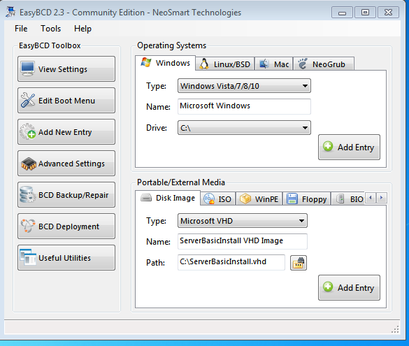
Set the path to point at your vhd file.
You can change the name to make it more descriptive of your file.
Select Add Entry in bottom right
Check the boot menu, and you can select the VHD as the default boot drive if you want.
easybcd changing-default-entry
Select Edit Boot Menu on left.
For the screen below, I had name the VHD as "VHD Image", and I have already installed NeoGrub, which I will discuss later.

You can also change the timeout time
Click Save Settings when done.
Reboot, and make sure the new boot menu works, and you can boot up your VHD from it.
You may have a problem booting the VHD.
I ran into a problem when I first tried to boot the VHD, associated with loading "winload.exe" on bootup.

The problem is described here, in the first post of the thread.
winload thread
It is caused by a mismatch in the dates of winload.exe and bootmgr.
You need to update bootmgr file to newer one (used by windows server 2012 R2).
Turn off your pc (if necessary). Connect your Server 2012 R2 OS disk to your pc. Boot up into windows 7, open file explorer and open the Server OK disk, probably d:.
bootmgr will be in the root directory.
Make a BOOT_BCD directory in the root directory of C
Right click on Computer, then select Manage, then Disk Management (under Storage on left),
Right click on the
System Reserved 100 MB partition
Select Change Drive
Letter and Paths…
Select Browse,
then + (to the left of C:\, to expand C:),
select BOOT_BCD, OK, ok


Now you can open the
BOOT_BCD directory with file explorer.

Rename the existing bootmgr to bootmgr.sav.
Answer yes and ok a
bunch of times to do this.
Copy the newer bootmgr
from the Server OS disk to BOOT_BCD
For me, the newer
bootmgr is dated 11/21/2014, older windows 7 version is 11/20/2010
reboot and make sure it
boots ok into the VHD with the new bootmgr file. It should boot with no problems.
Do not proceed unless you can boot up and run your VHD, booting up without the USB boot stick you made earlier.
CHECKPOINT
At this point, you should be able to boot up and run your VHD.Do not proceed unless you can boot up and run your VHD, booting up without the USB boot stick you made earlier.
FYI, it is now booting with information from the boot sector on the Windows 7 DD.
Now reboot back into Windows 7.
Finish VHD install, and Ram boot
OK, now you have a
working VHD of Windows Server, or whatever OS you are working with.
Now you need to the
following so you can load the OS into Ram, and run from Ram.
The rest of the
instructions assume you performed the previous instructions
"Make a BOOT_BCD
directory in the root directory of C"
If you can boot the VHD
without them, you don't have to copy the new bootmgr file, but you do need to
do the instructions up to that point, so you can open the BOOT_BCD directory.
Setup Firadisk and
disable Driver signature enforcement
Bootup the VHD.
Open internet explorer, and
download the winram files
unzip to your desktop to
folder named WinRAM. You should be able to drag and drop from the zip
file to do this.
Open WinRam folder, then
open the Firadisk directory.

Doubleclick on
TestSignRootCA.reg to run it
Doubleclick on
TESTSIGNING_ON.cmd to run it.
Right click on the
firadisk.inf file (setup information file type), and select install
Go to Control Panel,
then System, then Device Manager.
Click on Storage
Controllers, and make sure you see the FiraDisk Virtual Disk Emulator.
Reboot.
Boot may fail because Firadisk is not "signed"

If it fails, press Enter


Select "Disable Driver Signature Enforcement", and press Enter
It should boot into your VHD now.
You have to do this to
boot with Firadisk installed, until you fix a few things.
After Windows starts,
open a command window, and type the following:
bcdedit
-set Testsigning on
Close the command
window.
Open the WinRAM folder, then open the VHD_BCD directory
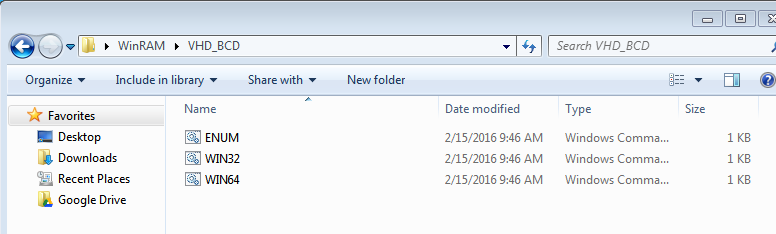
Select ENUM.cmd and
WIN64.cmd files, right click, and copy
Open the BCD_Boot directory, and paste the ENUM and WIN64 cmd files here
Drag and drop the BCD icon to on top
of ENUM.cmd
It will open a dos
window and run a script file
Drag and drop BCD to on top of WIN64.cmd
It will open a dos
window again, last two commands will fail, that is OK.
Reboot
into the VHD file on disk, and make sure the VHD file still boots up OK.
You should not have to go through the "Disable Driver Signature Enforcement" thing now.
You should not have to go through the "Disable Driver Signature Enforcement" thing now.
Add NeoGrub to boot OS from RAM
Reboot back into Windows
7
Open EasyBCD
To run an OS from RAM,
you need to use Grub4dos. But easyBCD has its own version of Grub called
NeoGrub that is easy to install and use. It just takes a few mouse clicks
to install
Here are the
instructions for NeoGrub
So, go to the "Add New
Entry" screen, select the NeoGrub tab in the top section, then install
NeoGrub.
Select
"Configure", and you get an edit screen. The screen lets you
edit what is the equivalent of the Grub menu.lst file.
Add the following, but
replace ServerbasicIntall.vhd with the name of your vhd. It would be “Audio_full.vhd”
if you followed the instructions literally.
#default to first entry
(title)
default 0
#set timeout in seconds
timeout 5
title Server2012 R2 - FiraDisk
RAMDISK
find --set-root
--ignore-floppies /ServerbasicInstall.vhd
map --mem
/ServerBasicInstall.vhd (hd0)
map --hook
root (hd0,0)
chainloader /bootmgr
Exit the program, and
reboot.
On the new startup boot
screen, select NeoGrub
This should take you to
a screen that lets you select Server2012 R2 - FiraDisk RAMDISK
Select this.
Booting will take a
while now, it has to load the OS into RAM.
You should now have an
OS that runs out of RAM.
At this point, you can
boot back into the VHD from the first boot up menu (the VHD file on disk), and
make changes. Any changes you make while running out of ram will be LOST
on the next bootup.
Configuring EasyBCD
Some other things you
can do now.
Boot windows 7 again,
and run EasyBCD
Select “Edit Boot Menu”
on left.
Check the default box by
NeoGrub to make it the default choice.
Change the “Boot default
OS after xx seconds” to whatever you want.
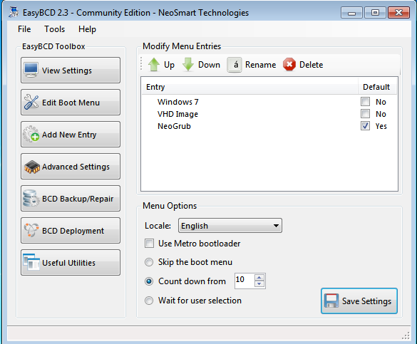
Click Save Settings.
Now, reboot.
Don’t do anything, it
will default to NeoGrub on bootup, and then in NeoGrub will default to the one
and only choice, because of these lines in the NeoGrub configuration file
Other information
If you have multiple VHD files you want to use, you can add lines to the end of the Neogrub configuration fileRun Windows 7, and open EasyBCD
Select Add New Entry on
left
Select NeoGrub button on
top
Select Configure button
Add these lines. The title line should be different from the
first title, make it descriptive for whatever this vhd file contains.
Change ServerXXX.vhd to
the name of your other vhd file.
title Server2012 R2 -
FiraDisk with XXX
find --set-root
--ignore-floppies /ServerXXX.vhd
map --mem /ServerXXX.vhd
(hd0)
map --hook
root (hd0,0)
chainloader /bootmgr
It will default to the
first choice, and if you don’t change the default timeout you will only have 5
seconds to pick this other choice on bootup.
My notes:
## default num
# Set the default entry to the entry number NUM. Numbering starts from 0, and
# the entry number 0 is the default if the command is not used.
#
# You can specify 'saved' instead of a number. In this case, the default entry
# is the entry saved with the command 'savedefault'.
# WARNING: If you are using dmraid do not use 'savedefault' or your
# array will desync and will not let you boot your system.
default 2
## timeout sec
# Set a timeout, in SEC seconds, before automatically booting the default entry
# (normally the first entry defined).
timeout 10
find
--set-root /Myl33t7.vhd
map /Myl33t7.vhd
(hd0)
root (hd0)
chainload
/BOOTMGR
Install windows 7
install windows
install chipset drive
install ethernet driver
setup home network
install renasys usb
driver
install amanero driver
download chrome
setup chrome
download drive
Change screen resolution
download and install
EasyBCD 2.3
Download bootice
unzip, and install to
desktop
rightclick on it, and
run as admin
select c: as the
destination disk
You can edit menu.lst in
BOOT_BCD folder
I used bootice to edit
menu.lst
For now, I left it.
Boot back into
Server2012
In WinRAM folder, open
VHD_BCD directory
Select ENUM.cmd and
WIN64.cmd, right click, and copy
Go to C:\Boot directory,
right click and paste, to copy ENUM and WIN64 files here
Drop and drag BCD on top
of ENUM.cmd
It will open a dos
window and run a script fild
Drop and drag BCD to
WIN64.cmd
It will open a dos
window again, last two commands will fail, that is OK.
Now you can boot from
RAM.
First, I would make sure
the VHD file still boots up OK.
reboot into Windows
Server, should boot from RAM now
Grub4Dos Install (not
required, for reference only)
Open winram folder, then
Grub4Dos folder,
change Install_gldr to
look like the following
The main change is this
line: Set STORE=C:\BOOT_BCD\Boot\BCD. I also deleted the echo off
line so you can make sure it works.
Setlocal
::Set path to
bcdedit.exe (e.g. C:\Windows\System32\bcdedit.exe)
Set
BCDEDIT=C:\Windows\System32\bcdedit.exe
::Set path to BCD Store
(e.g. C:\boot\BCD)
Set
STORE=C:\BOOT_BCD\Boot\BCD
for /f
"tokens=3" %%A in ('%BCDEDIT% /store %STORE% /create /d
"GRUB4DOS" /application bootsector') do set guid=%%A
%BCDEDIT% /store %STORE%
/set %guid% device boot
%BCDEDIT% /store %STORE%
/set %guid% path \grldr.mbr
%BCDEDIT% /store %STORE%
/displayorder %guid% /addlast
endlocal
pause
exit
copy grlder, grlder.mbr,
and menu.lst to BOOT_BCD folder (did not use Install_Grldr2)
Copy this to the screen
title Boot Windows 7
find --set-root /bootmgr
chainloader /bootmgr
save it as menu.lst in
the root directory.
Note that you can change
the title to whatever you want, just make sure the line starts with "title",
and this is case sensitive, so all lower case.
Make a copy of the grldr
and grldr.mbr files, and copy to your root drive.
reboot. You should
see a see a grub4dos menu on startup with the one option, Boot Windows 7 in my
case. Select it, and it should boot your os.
I had trouble the first
time I did this. I was messing with figuring out bootice, so this may
have caused my problem. I went through the steps again, and it worked
fine after doing it a second time, in this order.
Add the following to the
menu.lst file
title Server2012 R2 -
FiraDisk RAMDISK
find --set-root
--ignore-floppies /ServerbasicInstall.vhd
map --mem
/ServerBasicInstall.vhd (hd0)
map --hook
root (hd0,0)
chainloader /bootmgr
title basicVHD.vhd -
normal boot
find --set-root
/basicVHD.vhd
map /basicVHD.vhd (hd0)
map --hook
root (hd0, 0)
chainloader /bootmgr
Reboot. From
reboot screen, select NeoGrub.
If it won't boot up, you
may need to
Select the VHD, but push
F8, then select "Disable Driver Signature Enforcement"
Once it works, I would
make a copy of the vhd, and save it as a new baseline.
Now you can add other
drivers, programs, audiophile optimizer or whatever you want. You could
add them to your baseline, or make different versions of vhd with different
programs on them.
You can add the option
to boot multiple vhds into grub
example.
Edit menu.lst with
notepad
Open file explorer
Select menu.lst, then
select properties

Push Change button (after Opens with)
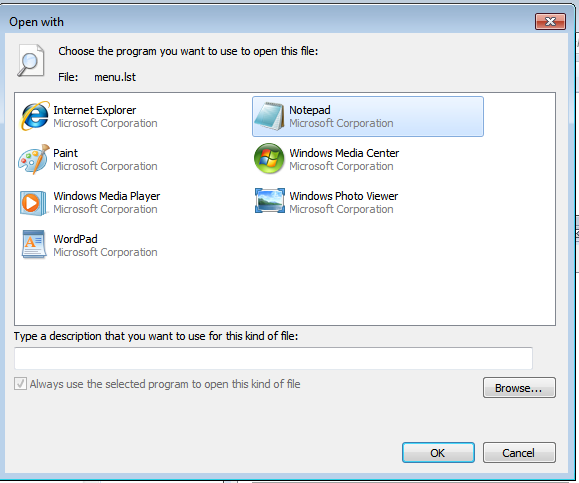
Select Apply in next Window.
Now, menu.lst will appear as menu, and if you right click you can edit with notepad
![]()